Map Sensor Honda Tps Sensor Wiring 1 YELLOW RED 2 GREEN BLUE 3 GREEN WHITE TPS SENSOR THE WAY IT WAS WIRED WHEN I BOUGHT IT ran crapty 1 SOLID GREEN 2 RED BLACK 3 YELLOW GREEN
A map sensor or manifold absolute pressure sensor is an integral part of any Honda s engine control unit ECU This tiny component helps the ECU determine how much air is entering the engine so it can regulate fuel delivery accordingly Using the Honda Map Sensor Wiring Diagram is simple Start by locating the correct wire for the part you re looking for Each wire has a color coded label that identifies it Once you have located the correct wire you can use the diagram to trace its path to the part you re trying to install or replace
Map Sensor Honda Tps Sensor Wiring

Map Sensor Honda Tps Sensor Wiring
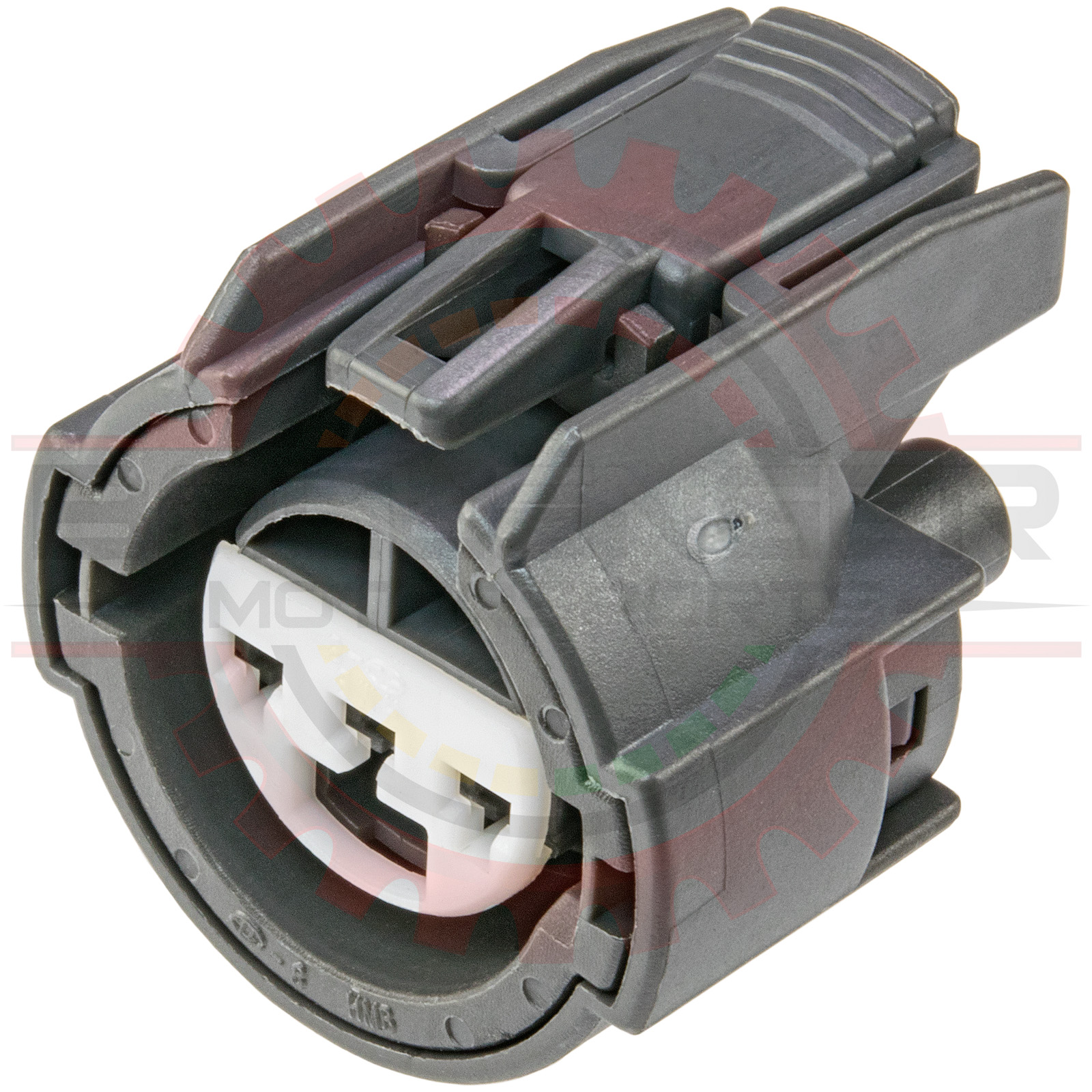
https://www.bmotorsports.com/shop/images/CONN-100893-1.jpg

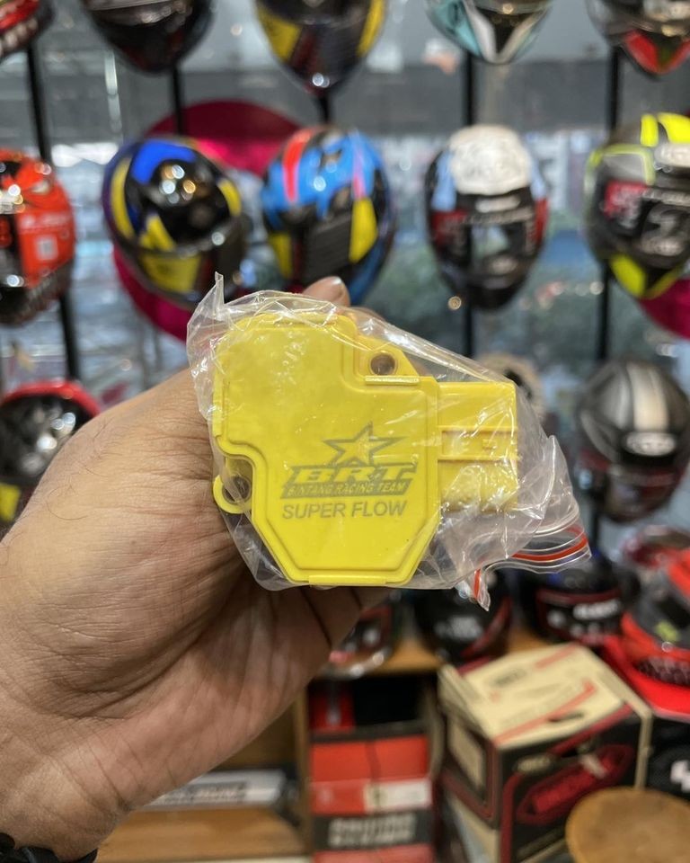
BRT TPS SENSOR Available For R15 CBR GSX
https://bongshal.com/public/uploads/all/RUGnHC981yEPRk497kTGGJRd8uDzYMMGYfymAhRj.jpg
MAP Sensor Wiring Honda Element Owners Club
https://www.elementownersclub.com/attachments/img_1962-jpg.217366/
A5 INJ3 INJECTOR 3 Blue Battery Voltage with KOEO A6 PO2SHTC O2 sensor heating element Org Wht Battery Voltage with KOEO A7 FLR1 fuel pump Grn BLK Battery Voltage with KOEO A8 empty A7 and A8 have the same circurt so they can be the same A9 IACV IAC valve Blk Blu About 10v KOEO on Warm engine A10 empty Determine the replacement MAP sensor wiring and splice the wiring into the factor harness Double check all connectors before switching the ignition on as most MAP sensors will burn out if you make a wiring mistake Plumbing in the MAP sensor Run a vacuum line from the intake manifold for the MAP sensor The MAP sensor must read the intake
This option replaces the MAP sensor with the TPS sensor for table indexing It is designed for use with individual throttle bodies where the MAP sensor does not accurately reflect the engine air flow This allows the throttle position sensor to be adjusted or re scaled to suit slight variations in TPS sensor position or range The normal Step 4 Calibrate the new throttle position sensor The correct voltage of the new TPS is 5 volts with no throttle and 4 5 volts with the throttle wide open The Brown Red wire center wire from the connector is what sends the voltage to the D11 position of the Engine Control Unit ECU telling it if the throttle is open or closed
More picture related to Map Sensor Honda Tps Sensor Wiring

Test A Throttle Position Sensor Using A Multimeter Or OBD II Scanner
https://i.ytimg.com/vi/9_LBQBmI_W4/maxresdefault.jpg

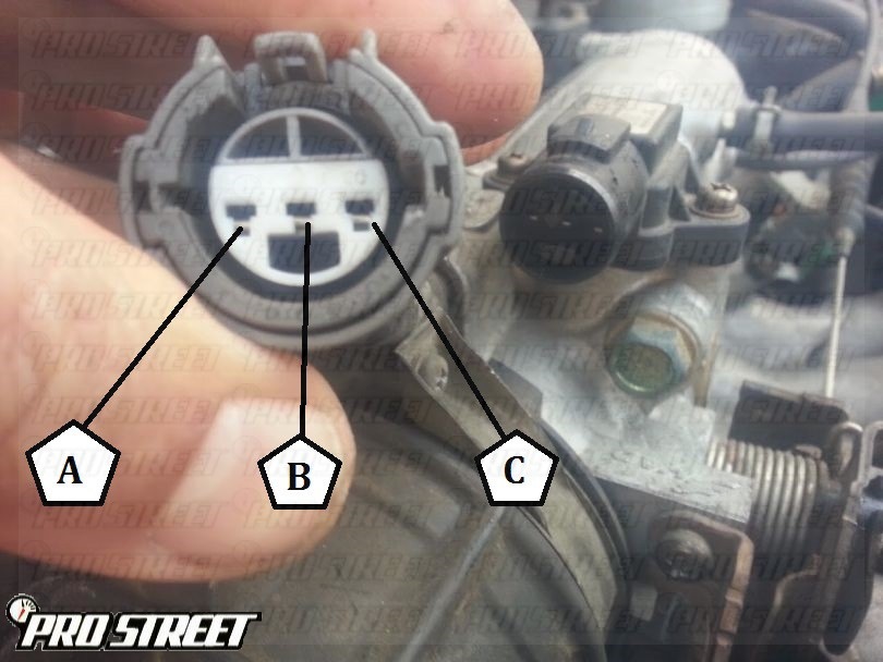
Honda Obd2 Map Sensor Wiring Wiring Diagram And Schematics
https://my.prostreetonline.com/wp-content/uploads/2015/02/how-to-service-acura-integra-map-sensor-3.jpg

Bosch Map Sensor Pinout Wiring Flow Schema
https://i1.wp.com/wagendass.com/36567-tm_thickbox_default/map-sensor-replacing-0261230030-0261230174-46553045-.jpg?strip=all
MAP Sensor Wiring Diagram NOTE The manifold absolute pressure MAP sensor wiring diagrams and info in this page apply only to 1996 1997 1998 1 6L Honda Civic The MAP sensor on your Civic can be tested with just a multimeter no scan tool required The following tutorial will help you with the test procedure on a step by step manner 1 Remove throttle body very straighforward remove 3 12mm bolts and 2 12mm nuts disconnect all vacuum lines disconnect TPS and MAP plugs disconnect intake Once these are off just lift the TB off the bolts studs and turn it on its side On the side facing the firewall you ll see the TPS 2
Jan 8 2008 1 I have a 92 EG Hatch with a JDM B16 My problem is that there are 2 map sensors One is wired directly to the ECU and the other is from the wiring harness Its a GSR harness and for some reason Vtec will only engage with the Map sensor that is directly from the ECU is hooked up But the car will not idle and I have to rev it to 10 Year Member Dec 17 2003 7 put the orange wore to the middle wire of the map and the green wire to the middle wire of the tps the tps is the one on the left side of the tb the middle wire cuz thier is a set of 3 wires always hook it up to the middle one

21 Map Sensor 1 15Bar MPXH6115AC6U Eezi4
https://eezi4.com/wp-content/uploads/2021/07/21_Map_1_Bar_smt-e1625234136735-1020x1024.png

Sensor Map Honda Crv Motor 2 0 Modelos 1997 2001 Denso 500 00 En
https://http2.mlstatic.com/sensor-map-honda-crv-motor-20-modelos-1997-2001-denso-D_NQ_NP_442225-MLM25405619560_032017-F.jpg
Map Sensor Honda Tps Sensor Wiring - Determine the replacement MAP sensor wiring and splice the wiring into the factor harness Double check all connectors before switching the ignition on as most MAP sensors will burn out if you make a wiring mistake Plumbing in the MAP sensor Run a vacuum line from the intake manifold for the MAP sensor The MAP sensor must read the intake