3 Pin Map Sensor Wiring Diagram To wire a 3 wire map sensor you need to connect the power wire to a 5 volt power source the ground wire to the vehicle s chassis and the signal wire to the appropriate input pin on the engine control unit ECU or a data logger
Mastering MAP Sensors Unveiling the Secrets of 3 4 Pin MAP Sensor Wiring Expert Tips for Proper Wiring Techniques In this comprehensive video we ll del Although the sensor technology may differ all 3 wire sensors are wired the same way A three wire sensor has 3 wires present two power wires and one load wire The power wires will connect to a power supply and the remaining wire to some type of load The load is a device that is being controlled by the sensor
3 Pin Map Sensor Wiring Diagram
3 Pin Map Sensor Wiring Diagram
https://www.team-integra.net/attachments/img_1092-jpg.106538/

Aem Map Sensor Wiring
https://i2.wp.com/s1.manualzz.com/store/data/009878776_1-cf46a5834bf478706dfdd288eb3813f6.png
DIAGRAM 1992 Chevy Truck Knock Sensor Wiring Diagram MYDIAGRAM ONLINE
https://www.pdfmanual4trucks.com/app/download/8252018815/Map_sensor_wire_diagram%25202+Isuzu+Ftr+Wiring+Diagram.JPG?t%5Cu003d1549518767
A well functioning MAP sensor ensures that your vehicle runs efficiently maintaining performance and reducing emissions Understanding the wiring diagram of a 3 wire MAP sensor can be incredibly beneficial whether you re troubleshooting an issue or simply want to understand your vehicle better The Basics of a 3 Wire MAP Sensor Wiring diagram for a GM 3 bar map sensor A GM 3 bar map sensor is a vital component in a vehicle s electronic engine management system It measures the intake manifold pressure which helps the engine control unit ECU optimize fuel injection and ignition timing Wiring the sensor correctly is crucial for proper functionality and accurate
Pin 1 seems to be ground as the diagram says so I ve measured with respect to that Pin 2 measures a steady 2 25v and Pin 4 a steady 1 83v both with the engine idling and off Pin 3 was varying quite a bit between 1v and 4 5v if i recall Wiring Diagram Info Request Map Sensor 3rd and 4th gen I have a 3rd gen engine wiring wit a cut map sensor I bought a 4th gen map sensor with pig tail On the gen4 the brown wire goes to ground pin 1 the gray wire is the 5V from the ECU pin 3 and the green black is the signal wire pin 2 Hope to help Sam Save Share
More picture related to 3 Pin Map Sensor Wiring Diagram

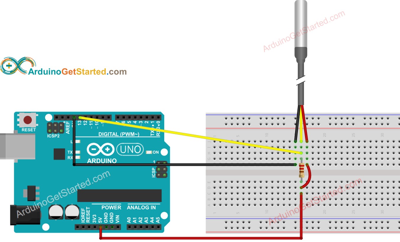
Vw 4 Pin Temperature Sensor Wiring Diagram Headcontrolsystem
https://headcontrolsystem.com/wp-content/uploads/2022/12/arduino-temperature-sensor-wiring-diagram.jpg

O2 Sensor Wiring Diagram For Your Needs
https://ww2.justanswer.com/uploads/s420/2009-10-17_025813_97_Mustang_HO2.jpg

Vw Map Sensor Wiring Diagram
https://i.pinimg.com/originals/15/b6/78/15b678df1756a156e90a470fee4b16a7.jpg
A 3 pin map sensor wiring diagram typically shows the sensor s three pins connected to corresponding wires in the vehicle s wiring harness The diagram will also illustrate the pathway of these wires to the ECU These diagrams are usually found in Using 3 Pin Map Sensor Wiring Diagrams for Troubleshooting Electrical Problems 1 Check for continuity between the sensor pins and the ECU to ensure a proper connection 2 Look for any signs of damage or wear on the wiring that may be affecting the sensor s performance 3 Compare the diagram with the actual wiring in your vehicle to spot
[desc-10] [desc-11]

VWVortex Map Sensor Plug With Wires
https://uploads.tapatalk-cdn.com/20160925/487477dd0b55df9579e8068264c6411d.jpg
![]()
Sensor Circuit Diagram Circuit Diagram
https://i2.wp.com/toshiba.semicon-storage.com/content/dam/toshiba-ss-v2/master/en/semiconductor/application/blood-glucose-meter/sensor-circuit_system-block-diagram_1_en.png?strip=all
3 Pin Map Sensor Wiring Diagram - [desc-14]